Parallel branches implement OR
This PLC programming example lets either of two buttons turn on the same lamp. Use it to understand parallel branches and to compare OR with the series AND exercise. The important change is the arrangement of paths, not the type of coil or the meaning of an input bit.
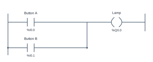
The reference has one NO contact on each of two parallel branches. Both paths join before the Lamp coil. If Button A is true, the upper path conducts. If Button B is true, the lower path conducts. Either complete path is enough, so the expression is Lamp = ButtonA OR ButtonB. One false branch cannot block another true branch.
This is inclusive OR: both inputs true also produce a true output. The four combinations are off for neither input, on for A alone, on for B alone, and on for both. Exclusive OR would require the output to be off with both inputs true; that is a different specification and is not what this reference implements.
The two branches feed one coil. You do not need two rungs that each write Lamp, and this simulator permits only one writer for each coil target. The reference expresses alternative reasons for one output to be on in a single place. As with Lamp Follow, releasing all active inputs turns the output off because there is no holding contact.
Try the program
- Open the simulator, click Run and begin with both buttons released. Follow the two paths visually and identify the point where they join before Lamp.
- Press A alone and observe Lamp. Release A, then press B alone. Both individual conditions should turn on the same output.
- Set both inputs true, then release one. Lamp should remain on through the other branch. Release the last active input and verify that the lamp turns off.
- Run the exercise tests, then compare this program with Two-Button AND. Keep the input bindings the same while changing their arrangement to see exactly why the truth table changes.
Use Load reference to restore the supplied solution, or Start blank to build your own. The reference is a working starting point, so passing tests before editing does not mean you have built the circuit yourself. Use the diagram, input values and test results together to explain each output change.
Practice challenge
Write the four input combinations and their expected outputs before running. Then consider a third alternative input on another branch: would either original button still work by itself? Explain your answer by tracing a complete path from the left rail to the shared coil. Return to the original two-input program and check that releasing one button cannot turn the lamp off while the other input remains true. No stored memory is needed for that result.
Three common mistakes
Adding both contacts in series
A single path through both contacts requires A AND B. If neither individual button lights the lamp, inspect whether you created a second branch or just added another contact to the first.
Adding a second Lamp coil
Use parallel input paths feeding one output. Two separate coils writing the same variable are rejected by this teaching environment and make the output ownership harder to follow.
Expecting both buttons to cancel each other
OR includes the both-true combination. A lamp that goes off when both buttons are pressed would implement a different function. Read the goal and check all four input combinations before changing the program.
Questions about this example
What is the difference between AND and OR in ladder logic?
AND uses contacts in series so every condition must pass. OR uses parallel paths so any complete path can pass. Both arrangements can use the same NO instructions and the same output coil.
Why does the lamp remain on after I release A?
Check Button B. If B is still true, its branch continues to energize the coil. This is a current input condition, not a stored latch.
Where does a parallel branch appear next?
Motor Start/Stop uses a Start branch in parallel with a MotorRun feedback branch. That adds memory while a stop permissive remains common to both paths.
Keep practicing
Review ladder logic basics, or compare this program with a related example:
All addresses and devices here are virtual. See supported instructions and limitations for the teaching subset, timing model and boundaries of the simulator.