Two thresholds prevent cycling
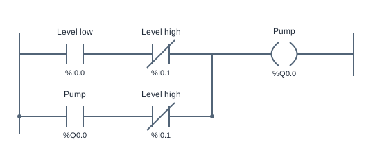
This tank level control ladder logic example uses a self-latching pump command and two level conditions. LevelLow starts filling, LevelHigh stops filling, and the region between them preserves the previous pump state. This behavior is called hysteresis: the turn-on and turn-off decisions use different thresholds.
The expression is Pump = (LevelLow OR Pump) AND NOT LevelHigh. LevelLow provides the start path, Pump provides feedback, and the high-level condition blocks both. The reference repeats the NC LevelHigh instruction in each branch so the stop condition applies to the start path and the holding path alike.
Here LevelLow means the low-level condition is active, rather than an arbitrary electrical sensor wiring state. When LevelLow is true and LevelHigh is false, the pump turns on. As the level moves above the low threshold, both input conditions can be false. The feedback contact then keeps filling until LevelHigh becomes true.
After the high condition clears, both inputs may again be false, but the pump remains off because its feedback bit was cleared. The same pair of input values can therefore produce a different result depending on the previous state. That is the important difference between hysteresis and a purely combinational AND or OR program.
High level has priority if both conditions are true. Although the normal level model should not need that combination, the Boolean program still has a clear result: Pump is false. Read sensor names as their defined process conditions and consult the I/O table before choosing a NO or NC instruction. The NC instruction here checks that LevelHigh is false.
Try the program
- Open the simulator and run the reference. Start with the pump off and inspect LevelLow, LevelHigh and Pump. Locate both parallel branches and their high-level checks.
- Observe a low-level condition start filling. While the level is between thresholds, confirm that the pump stays on even though LevelLow is no longer true.
- Observe LevelHigh stop the pump. As the level returns between thresholds, confirm the pump stays off until the low-level start condition returns.
- Run the supplied acceptance cases for starting, holding, stopping, remaining off and refilling. Compare the middle-band result before and after a high-level stop to see the stored state.
Use Load reference to restore the supplied solution, or Start blank to build your own. The reference is a working starting point, so passing tests before editing does not mean you have built the circuit yourself. Use the diagram, input values and test results together to explain each output change.
Practice challenge
Write down two histories that both end with LevelLow and LevelHigh false. In one, start with a low-level fill; in the other, begin after a high-level stop. Predict Pump for each and explain why identical present inputs do not imply identical outputs when feedback stores the preceding state. Compare with the memoryless AND example to make the distinction explicit.
Three common mistakes
Driving Pump directly from LevelLow
The pump stops as soon as the low condition clears, so it never intentionally fills to the high threshold. Add the feedback path to hold the running state through the middle band.
Checking LevelHigh only on the start branch
An unrestricted Pump feedback branch can keep filling after high level is reached. The high-level blocking condition belongs on every path that could energize the pump.
Expecting the middle band to have one fixed output
Between thresholds, the pump should retain its preceding state. Test both directions: while filling it stays on, and after the high-level stop it stays off. One snapshot does not demonstrate hysteresis.
Questions about this example
What is hysteresis in PLC control?
Hysteresis uses different turn-on and turn-off thresholds and remembers the current state between them. Here low level starts the pump and high level stops it.
Why is LevelHigh a NC instruction?
The rung needs permission while LevelHigh is false. A NC instruction performs that Boolean inversion. This says nothing by itself about the physical sensor wiring.
How is this related to motor self-latching?
Both use output feedback to hold a state. Motor Start/Stop uses operator commands; the tank uses low and high process conditions. In each case the stop condition must override the holding path.
Keep practicing
Review ladder logic basics, or compare this program with a related example:
All addresses and devices here are virtual. See supported instructions and limitations for the teaching subset, timing model and boundaries of the simulator.