Sequence three timed phases
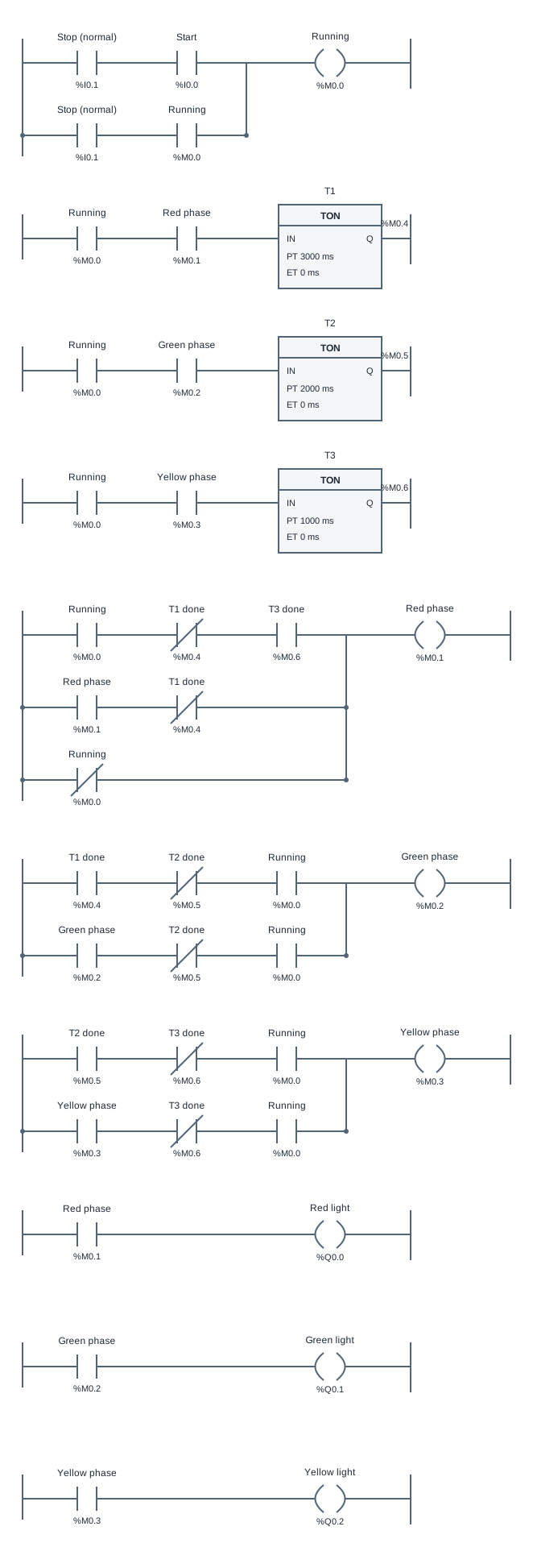
This traffic light PLC example combines a run latch, three TON timers and internal phase bits. The sequence is Red for 3 seconds, Green for 2 seconds, Yellow for 1 second, then back to Red. It is a larger program to read rung by rung after learning contacts, self-latching and timers separately.
The run latch accepts Start while StopOK is true. Internal bits p1, p2 and p3 represent the Red, Green and Yellow phases. Timers T1, T2 and T3 measure the active phase using presets of 3000, 2000 and 1000 ms. Their done bits trigger transitions rather than directly turning every lamp on independently.
Phase memory connects the timed intervals into a repeating sequence. The current phase holds until its timer completes, then the next phase becomes active. Output rungs near the bottom map phase bits to Red, Green and Yellow. Separating the state from the visible lamps makes it easier to inspect why the program chose an output.
Rungs evaluate from top to bottom and writes are visible to later rungs in the same scan. Moving a timer or phase rung can therefore change transition behavior. Read the supplied reference in order and observe internal bits at the changeover. Mutual exclusion means conflicting lights must not be on together, including during transitions rather than only at steady states.
Pressing Stop clears the running state, resets enabled timing and returns the example to Red with Green and Yellow off. With Start released, releasing Stop does not resume the old phase. A new Start begins a full Red dwell. This model is for sequencing practice and does not represent certified road traffic control.
Try the program
- Open the simulator and inspect the initial state: Red on, Green and Yellow off. Find run, p1, p2, p3 and timer done bits in the variable table before starting the cycle.
- Click Run, press and release Start, and observe a complete Red → Green → Yellow → Red sequence. Compare each lamp with its phase bit and the corresponding timer ET.
- Press Stop during each phase. Check that the output returns to Red and the other lamps turn off. Release Stop with Start released, then issue a fresh Start and observe the Red delay.
- Run the acceptance cases for exact dwell times, repeated cycles and stop/restart behavior. When experimenting with the program, change one rung at a time so a scan-order change is easier to explain.
Use Load reference to restore the supplied solution, or Start blank to build your own. The reference is a working starting point, so passing tests before editing does not mean you have built the circuit yourself. Use the diagram, input values and test results together to explain each output change.
Practice challenge
Pause near a phase change and inspect the active phase bit, timer elapsed time and done bit. Predict which output rung will see the new state later in the scan. Compare your prediction with the next single scan, then follow the next phase timer. The aim is to explain one transition in full rather than simply watching the six-second animation repeat.
Three common mistakes
Timing all lamps from Start alone
Timers driven only by a common start condition run together instead of measuring separate phases. Each phase timer needs the running condition and its own phase enable.
Setting a new phase without clearing the old one
Two active phase bits can energize conflicting outputs. Observe transitions and check the conditions that end the previous phase, not just the condition that starts the next.
Ignoring rung order
This engine exposes writes to later rungs in the same scan. Reordering phase and timer logic can change boundary behavior even when the individual contacts look unchanged. Compare with the reference order.
Questions about this example
How long is a complete cycle?
The specified running cycle is 3 + 2 + 1 = 6 seconds of simulation time. The supplied cases check scan boundaries as well as repeating behavior.
Why use internal phase bits?
They store which part of the sequence is active. Timers measure that state and output rungs display it, which makes a multi-step process easier to inspect and reason about.
What should Stop do during Green?
It should clear running and return to Red with Green and Yellow off. With Start released, the old Green phase should not resume simply because Stop is released.
Keep practicing
Review ladder logic basics, or compare this program with a related example:
All addresses and devices here are virtual. See supported instructions and limitations for the teaching subset, timing model and boundaries of the simulator.