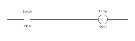
One contact, one coil
This beginner ladder logic example connects a momentary input to a lamp output. It is the smallest complete program in PLC Practice Lab: one normally-open contact, one coil, and no stored running state. Use it to learn what a rung means before adding branches, timers or counters.
Read the reference diagram from left to right. The Switch contact checks the Switch Boolean variable. A normally-open instruction passes the logical condition when that variable is true. The Lamp coil writes the resulting condition to the output. The relationship is simply Lamp = Switch. The lines represent logical continuity, not an electrical supply inside your browser.
The engine evaluates the program in fixed 20 ms logic scans. With Run active, a pressed Switch is read on a scan and the Lamp output becomes true. Releasing the button makes the input false, so the coil is written false on a subsequent scan. The coil does not remember an earlier press. A paused simulation does not keep evaluating new input changes.
The I/O assignment below the reference identifies Switch as a virtual input and Lamp as a virtual output. Their addresses help you distinguish what the operator changes from what the program controls. A contact reads a variable; a coil writes one. You can rename a symbol in the editor without changing this fundamental direction of information flow.
Try the program
- Open the simulator and click Run. Leave Switch released and confirm that Lamp is off. This establishes the initial condition before checking the active condition.
- Press and hold Switch in the device panel. Watch the powered path and the Lamp output. Release Switch and confirm that both return to the inactive condition.
- Pause the program, select the Switch contact, and inspect its variable and instruction type. Resume before judging whether changes to the physical input affect the output.
- Run the built-in exercise tests. They check the initial off state, the pressed state and the release transition. Then try Start blank, rebuild the single rung, and run the tests again.
Use Load reference to restore the supplied solution, or Start blank to build your own. The reference is a working starting point, so passing tests before editing does not mean you have built the circuit yourself. Use the diagram, input values and test results together to explain each output change.
Practice challenge
Before running, write the two possible Switch values and predict Lamp for each. Change the contact to NC and predict the new pair of results. Then run both versions and explain which one matches the original goal. Finally restore NO, build the rung from blank and check it again. This separates understanding a contact from merely recognizing the appearance of the supplied solution.
Three common mistakes
Using an NC instruction
A normally-closed instruction passes when Switch is false. That inverts the required behavior: the lamp is on while the button is released. Use NO for this exercise, then deliberately try NC to see the difference.
Binding the coil to the input
The contact should read Switch and the output coil should write Lamp. Check the symbol names and I/O table rather than assuming two similar-looking symbols refer to the same variable.
Expecting the lamp to stay on
A momentary button returns to false on release. This program has no holding branch, so turning off is correct. If you want a press-and-release start command, study Motor Start/Stop instead of changing the expected result here.
Questions about this example
Is a NO contact the same as a physical NO button?
The instruction checks whether a bit is true. A physical NO button describes electrical hardware. They match conveniently in this exercise because pressing Switch makes its input bit true, but the two concepts should be kept separate.
Why does nothing change while the simulation is paused?
Pause freezes program evaluation. Resume with Run so the next scans can read the input and update the output. Changing the input alone does not execute the rung.
What should I learn next?
Try Two-Button AND to require two conditions, or Either-Button OR to allow alternative paths. Both extend the same contact-to-coil relationship without introducing memory.
Keep practicing
Review ladder logic basics, or compare this program with a related example:
All addresses and devices here are virtual. See supported instructions and limitations for the teaching subset, timing model and boundaries of the simulator.